- 您现在的位置:买卖IC网 > Sheet目录3833 > AT87251G2D-3CSUM (Atmel)IC 8051 MCU 32K OTP 24MHZ 40DIP
39
AT/TSC8x251G2D
4135F–8051–11/06
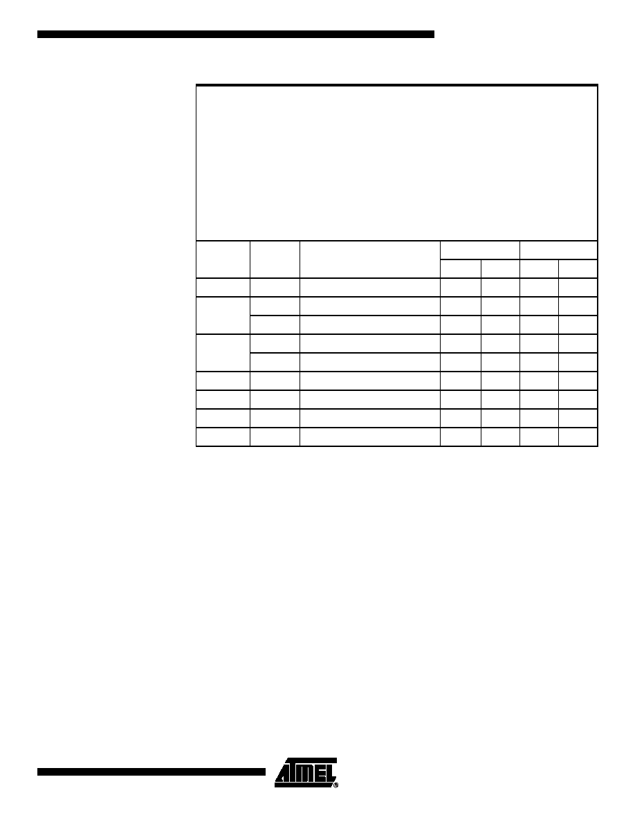
Table 32.
Summary of Call and Return Instructions
Notes: 1. A shaded cell denotes an instruction in the C51 Architecture.
2. In internal execution only, add 1 to the number of states if the destination/return
address is internal and odd.
3. Add 2 to the number of states if the destination address is external.
4. Add 5 to the number of states if INTR = 1.
Absolute callACALL <src>(PC)
← (PC) +2; push (PC)15:0;
(PC)10:0 ← src opnd
Extended callECALL <src>(PC)
← (PC) + size (instr); push (PC)23:0;
(PC)23:0 ← src opnd
Long callLCALL <src>(PC)
← (PC) + size (instr); push (PC)15:0;
(PC)15:0 ← src opnd
Return from subroutineRETpop (PC)15:0
Extended return from subroutineERETpop (PC)23:0
Return from interruptRETIIF [INTR = 0] THEN pop (PC)15:0
IF [INTR = 1] THEN pop (PC)23:0; pop (PSW1)
Trap interruptTRAP(PC)
← (PC) + size (instr);
IF [INTR = 0] THEN push (PC)15:0
IF [INTR = 1] THEN push (PSW1); push (PC)23:0
Mnemonic
<dest>,
<src>
(1)
Comments
Binary Mode
Source Mode
Bytes
States
Bytes
States
ACALL
addr11
Absolute subroutine call
2
9(2)(3)
29(2)(3)
ECALL
at DRk
Extended subroutine call (indirect)
3
14(2)(3)
213(2)(3)
addr24
Extended subroutine call
5
14(2)(3)
413(2)(3)
LCALL
at WRj
Long subroutine call (indirect)
3
10(2)(3)
29(2)(3)
addr16
Long subroutine call
3
9(2)(3)
39(2)(3)
RET
Return from subroutine
1
7(2)
17(2)
ERET
Extended subroutine return
3
9(2)
28(2)
RETI
Return from interrupt
1
7(2)(4)
17(2)(4)
TRAP
Jump to the trap interrupt vector
2
12(4)
111(4)
发布紧急采购,3分钟左右您将得到回复。
相关PDF资料
AT80C51RA2-SLSUM
IC 8051 MCU ROMLESS 44PLCC
AT80C51RA2-SLSUL
IC 8051 MCU ROMLESS 44PLCC
AT80C51RA2-RLTUM
IC 8051 MCU ROMLESS 44VQFP
213931-5
CONN JACKSCREW RECEPT 34 POS
AT80C51RA2-RLTUL
IC 8051 MCU ROMLESS 44VQFP
AT80C51RA2-3CSUM
IC 8051 MCU ROMLESS 40DIP
AT80C51RA2-3CSUL
IC 8051 MCU ROMLESS 40DIP
AT80C31X2-SLSUM
IC 8031 MCU ROMLESS 44PLCC
相关代理商/技术参数
AT87251G2D-RLTUL
制造商:ATMEL 制造商全称:ATMEL Corporation 功能描述:B/16-BIT MICROCONTROLLER WITH SERIAL COMMUNICATION INTERFACES
AT87251G2D-RLTUM
功能描述:8位微控制器 -MCU 251G2D 8/16bitC OTP 5V RoHS:否 制造商:Silicon Labs 核心:8051 处理器系列:C8051F39x 数据总线宽度:8 bit 最大时钟频率:50 MHz 程序存储器大小:16 KB 数据 RAM 大小:1 KB 片上 ADC:Yes 工作电源电压:1.8 V to 3.6 V 工作温度范围:- 40 C to + 105 C 封装 / 箱体:QFN-20 安装风格:SMD/SMT
AT87251G2D-SLSUL
功能描述:8位微控制器 -MCU Microcontroller
RoHS:否 制造商:Silicon Labs 核心:8051 处理器系列:C8051F39x 数据总线宽度:8 bit 最大时钟频率:50 MHz 程序存储器大小:16 KB 数据 RAM 大小:1 KB 片上 ADC:Yes 工作电源电压:1.8 V to 3.6 V 工作温度范围:- 40 C to + 105 C 封装 / 箱体:QFN-20 安装风格:SMD/SMT
AT87251G2D-SLSUM
功能描述:8位微控制器 -MCU OTP 8/16bit St 5V 24MHz RoHS:否 制造商:Silicon Labs 核心:8051 处理器系列:C8051F39x 数据总线宽度:8 bit 最大时钟频率:50 MHz 程序存储器大小:16 KB 数据 RAM 大小:1 KB 片上 ADC:Yes 工作电源电压:1.8 V to 3.6 V 工作温度范围:- 40 C to + 105 C 封装 / 箱体:QFN-20 安装风格:SMD/SMT
AT875
制造商:POSEICO 制造商全称:POSEICO 功能描述:PHASE CONTROL THYRISTOR
AT875LT
制造商:POSEICO 制造商全称:POSEICO 功能描述:PHASE CONTROL THYRISTOR
AT875LTS44
制造商:POSEICO 制造商全称:POSEICO 功能描述:PHASE CONTROL THYRISTOR
AT875S44
制造商:POSEICO 制造商全称:POSEICO 功能描述:PHASE CONTROL THYRISTOR